Lumetra Lumetra

How to Choose the Right Pluggable Optical Transceiver

Time:2026-09-21 Author:Amelia
0%

Choosing the right pluggable optical transceiver begins with the network’s real operating conditions. Distance matters, but it is only one part of the decision. A 10G module for a short data-center link behaves differently from a 400G module serving a regional connection. Fiber type, connector design, wavelength, reach, power draw, and temperature range must work together. A mismatch can appear as packet loss, unstable links, or an optical budget that looks acceptable on paper but fails in the rack.

Peter Winzer, a leading optical-communications researcher, has observed, “The future of communications is optical.” That view remains practical today. Optical capacity continues to support cloud platforms, enterprise networks, and high-performance computing. However, choosing a pluggable optical transceiver requires more than following speed labels. Network engineers should compare the switch port standard, fiber infrastructure, interoperability requirements, digital diagnostic monitoring, and supplier documentation. They should also verify whether the module supports the intended transmission distance under actual installation conditions.

Small details matter. A crowded cabinet may reject a low-power design with poor thermal behavior. A long fiber route may expose weaknesses in an underestimated loss budget. Compatibility lists are useful, but they are not absolute guarantees. Field testing still matters.

The right choice is rarely the most expensive module. It is the one that fits the complete link. Mistakes happen, even after careful planning. This guide examines the practical checks that make those mistakes less likely.
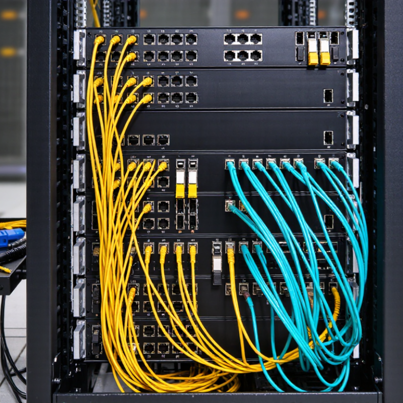
How to Choose the Right Pluggable Optical Transceiver

Understanding Pluggable Optical Transceiver Types and Applications

Choosing the right pluggable optical transceiver starts with the application, not the connector. A short access link may need an SFP or SFP28 module for 1G or 25G Ethernet. Server rows often use QSFP28 at 100G, while dense AI fabrics increasingly evaluate QSFP-DD or OSFP at 400G and 800G.

Single-mode fiber suits longer campus and metro paths; multimode fiber usually fits shorter data-center runs. Duplex optics send and receive over paired fibers, while parallel optics use multiple lanes. That difference changes cabling, polarity, and fault diagnosis.

The ITU’s Facts and Figures 2023 counted 5.4 billion Internet users, representing 67% of the global population. TeleGeography’s 2024 Global Bandwidth Research Service reported 29% growth in used international bandwidth from 2023 to 2024.

Capacity pressure is real, but it does not justify buying the fastest module.

Check link length, fiber type, wavelength, lane rate, FEC, power budget, and host compatibility.

For a 500-meter single-mode connection, a short-reach multimode optic is the wrong tool. For metro or data-center interconnects, coherent pluggables such as 400ZR or ZR+ can reduce transport equipment, but they require careful dispersion and power planning.

Digital diagnostics matter in practice. Temperature, received power, and bias current can reveal a dirty connector before downtime spreads. I have seen designs fail because a port supported the speed but not the module’s electrical form factor. That mistake is easy to make.

Published compliance data helps, yet interoperability testing remains more reliable than assumptions. Leave thermal headroom in tightly packed cages.

My checklist still needs improvement.

Matching Fiber Standards, Wavelengths, and Transmission Distances

How to Choose the Right Pluggable Optical Transceiver

Matching Fiber Standards, Wavelengths, and Transmission Distances

Selecting a pluggable optical transceiver starts with the installed fiber, not the data rate alone. Single-mode fiber usually supports longer links, while multimode fiber suits shorter data-center runs. ITU-T G.652.D identifies 1310 nm and 1550 nm as important windows for standard single-mode fiber. Wavelength mismatch can cause loss, dispersion, or complete link failure. Check the fiber type, connector, and switch interface together.

Transmission distance needs a practical margin. IEEE 802.3 specifications define different reach limits for Ethernet interfaces, often from 100 meters to 40 kilometers. A 10-kilometer module may not perform reliably across a damaged or heavily patched route. Cisco’s Annual Internet Report projected global IP traffic would reach 396 exabytes per month by 2022. Higher traffic makes stable, scalable links more valuable. Still, many installations overbuy distance. That wastes budget and may complicate troubleshooting.

Tips: Record the route length, fiber grade, connector count, and operating temperature. Then compare the module’s reach rating with real conditions. Verify wavelength compatibility at both ends. Also check digital diagnostics. They reveal temperature, optical power, and warning trends. I have seen “compatible” links fail after a simple patch-panel change. Specifications are useful, but site records are often incomplete. That is where careful verification matters.

Checking Data Rates, Form Factors, and Equipment Compatibility

How to Choose the Right Pluggable Optical Transceiver

Data rate is the first checkpoint, but it is not the only one. A transceiver must match the equipment port speed and signaling standard. A module rated for 10 Gb/s may not work in a port designed for 1 Gb/s operation. Check the switch, router, or server manual before ordering. Then compare the required distance, fiber type, connector, and wavelength. A 300-meter multimode link needs a different optical design from a 10-kilometer single-mode link. Measure twice.

Form factor also affects compatibility. Common sizes include SFP, SFP+, SFP28, QSFP+, and QSFP28. Their shapes may look similar, but their electrical lanes and thermal limits differ. A larger module cannot always replace a smaller one. Check the cage size, port spacing, breakout requirements, and available power. I have seen installations fail because the transceiver fitted physically but exceeded the equipment’s power budget. The mistake was small.

Review the equipment’s compatibility list and firmware requirements. Some systems verify module identification before enabling the port. Confirm supported coding, operating temperature, digital monitoring, and alarm functions. For difficult links, inspect transmit power, receiver sensitivity, and optical loss calculations. Leave safety margin for connectors, patch panels, and aging fiber. Documentation is useful, but field conditions can disagree. Record the exact port, distance, fiber route, and measured loss before making the final choice.

Evaluating Power Use, Temperature Ratings, and Network Conditions

Choosing a pluggable optical transceiver requires more than matching speed and connector type. Power use matters at scale. The IEA’s Electricity 2024 report estimates that data centers consumed about 460 TWh globally in 2022. Demand could exceed 1,000 TWh by 2026. A transceiver using one extra watt may seem minor. In a dense rack, it increases heat and operating cost. Check typical and maximum power ratings, not only the headline figure.

Temperature ratings must match the real installation. ASHRAE TC 9.9 recommends an inlet temperature range of 18–27°C for common data-center equipment. Outdoor cabinets, poorly ventilated rows, and sealed enclosures can exceed that range quickly. Select commercial, extended, or industrial temperature options according to measured conditions. Read the module’s operating limits carefully. A low-cost choice can become an unstable choice. I have seen teams trust room temperature while ignoring airflow near the cage. That assumption deserves review.

Tips: Measure inlet temperature beside the transceiver, during peak traffic. Confirm the host platform supports the module’s power class and coding. Then examine network conditions, including reach, fiber type, connector loss, and link budget. The Ethernet Alliance’s published roadmaps show rising speeds and tighter power constraints, so future capacity should influence today’s selection. Keep a small margin for dust, aging, and imperfect installation. Five extra meters of fiber rarely matter alone. Poor cleaning can matter much more.

How to Choose the Right Pluggable Optical Transceiver - Evaluating Power Use, Temperature Ratings, and Network Conditions

Transceiver Type Typical Data Rate Common Wavelength Typical Reach Typical Power Use Temperature Rating Fiber or Cable Suitable Network Conditions Selection Notes
1G Short-Reach Optical Module 1.25 Gb/s 850 nm Up to 550 m on OM2/OM3 multimode fiber Typically 0.8–1.5 W Commercial: 0–70°C
Industrial: −40–85°C
Duplex multimode fiber Building access networks, server rooms, and short campus links A practical low-power choice when the link is short and the equipment is indoors.
10G Short-Reach Optical Module 10.3125 Gb/s 850 nm Up to 300 m on OM3 fiber; up to 400 m on OM4 fiber Typically 0.8–1.5 W Commercial: 0–70°C
Industrial: −40–85°C
Duplex multimode fiber Top-of-rack connections, data-center interconnects, and high-speed LANs Check the installed fiber grade and total connector loss before selecting the reach class.
10G Single-Mode Long-Reach Module 10.3125 Gb/s 1310 nm Up to 10 km on single-mode fiber Typically 1.0–1.5 W Commercial: 0–70°C
Industrial: −40–85°C
Duplex single-mode fiber Metro access, campus backbones, and inter-building links Allow a power budget for fiber attenuation, splices, connectors, and aging.
25G Short-Reach Optical Module 25.78 Gb/s 850 nm Up to 70 m on OM3 fiber; up to 100 m on OM4 fiber Typically 1.5–2.5 W Commercial: 0–70°C
Industrial: −40–85°C
Duplex multimode fiber High-density server access and short data-center links Verify switch port support, forward-error-correction requirements, and thermal headroom.
25G Single-Mode Long-Reach Module 25.78 Gb/s 1310 nm Up to 10 km on single-mode fiber Typically 2.0–4.0 W Commercial: 0–70°C
Industrial: −40–85°C
Duplex single-mode fiber Data-center interconnects, mobile transport, and campus backbones Higher throughput increases heat output; check chassis airflow and port power limits.
40G Parallel Short-Reach Module 41.25 Gb/s 850 nm Up to 100 m on OM3 fiber; up to 150 m on OM4 fiber Typically 1.5–2.5 W Commercial: 0–70°C
Industrial: −40–85°C
8-fiber or 12-fiber multimode MPO/MTP-style link Leaf-spine data-center switching and short high-density links Confirm polarity, fiber count, connector type, and breakout compatibility.
100G Parallel Short-Reach Module 103.1 Gb/s 850 nm Up to 70 m on OM3 fiber; up to 100 m on OM4 fiber Typically 2.5–4.0 W Commercial: 0–70°C
Industrial: −40–85°C
8-fiber multimode MPO/MTP-style link Short-distance spine-leaf connections and high-density switching Use when the link is short and parallel-fiber infrastructure is already available.
100G Single-Mode Duplex Module 103.1 Gb/s 1310 nm Up to 10 km on single-mode fiber Typically 3.5–6.0 W Commercial: 0–70°C
Industrial: −40–85°C
Duplex single-mode fiber Metro links, data-center interconnects, and long campus connections Select only after confirming optical power budget, dispersion limits, and host compatibility.
100G Coherent Long-Haul Module 100 Gb/s C-band, commonly around 1550 nm Tens to hundreds of kilometers, depending on the optical system Typically 12–25 W Usually commercial: 0–70°C; extended ratings vary Single-mode fiber with line-system support Regional transport, data-center interconnects, and optical backbone networks Requires careful planning for cooling, dispersion, optical line compatibility, and system-level power.
Planning reminder: Actual power consumption, reach, and temperature performance depend on the module design, host equipment, fiber loss, connector loss, airflow, and operating conditions. Always verify the equipment documentation and the complete optical link budget before deployment.

Comparing Reliability, Compliance, Cost, and Long-Term Support

Choosing a pluggable optical transceiver starts with the link, not the product label. In a live data center, I check fiber type, reach, connector, wavelength, and port speed before comparing prices. A module that fits physically may still fail during testing. Measure the optical budget carefully. Leave margin for patch panels, aging, and dirty connectors. Small details matter.

Reliability should be supported by evidence, not confident wording. Request test reports, operating-temperature data, digital diagnostics, and failure-rate information. Confirm the module meets applicable optical, electrical, safety, and environmental requirements in your region. Do not treat a compliance mark as proof of field performance. I have seen low-cost units create hidden expenses through unstable links, repeated replacements, and emergency labor. Purchase price is only one part of cost. Warranty coverage, return procedures, and spare inventory also affect the real budget.

Long-term support deserves equal attention. Ask whether firmware updates, compatibility records, installation guides, and lifecycle notices will remain available. Support should respond with practical troubleshooting steps, not copied specifications. A clear replacement process can protect a network during a midnight failure. One weakness in my own earlier evaluations was trusting a strong datasheet too quickly. Field conditions exposed connector contamination and temperature changes that laboratory figures did not reveal. The better choice balances compliance, dependable operation, total cost, and support that remains useful years later.

How to Choose the Right Pluggable Optical Transceiver

Comparing reliability, compliance, cost efficiency, and long-term support across common Ethernet optical transceiver types.

Scores use a 0–100 selection index based on typical IEEE Ethernet applications, commonly supported SFF management standards, deployment reach, thermal considerations, relative module cost, and expected lifecycle availability. Higher scores indicate a stronger overall fit; actual results depend on the network environment and supplier qualification.

FAQS

How should I choose a pluggable optical transceiver?

Start with the application and link distance. Check speed, fiber type, wavelength, lane rate, and host compatibility. Do not choose by connector alone.

Which module types suit different Ethernet speeds?

SFP modules commonly support 1G links. SFP28 modules suit 25G connections. QSFP28 often supports 100G. Higher-density 400G and 800G systems may use newer multi-lane formats.

When should I use single-mode or multimode fiber?

Single-mode fiber fits longer campus, metro, and inter-building paths. Multimode fiber usually suits shorter data-center runs. A 500-meter single-mode link needs the correct long-reach optic.

What is the difference between duplex and parallel optics?

Duplex optics transmit and receive through two separate fibers. Parallel optics use multiple lanes. This changes cabling, polarity, and troubleshooting methods.

What should I verify before installation?

Check the optical budget, connector type, wavelength, FEC, power use, and port compatibility. Inspect patch panels and connectors carefully. Tiny contamination can disrupt a link.

Are coherent pluggables suitable for metro connections?

Coherent pluggables can simplify some 400G metro and interconnect deployments. They require careful planning for dispersion, power, and thermal limits. They are not automatically the best choice.

How can digital diagnostics help network maintenance?

Diagnostics can show temperature, received power, and transmitter bias current. These readings may reveal a dirty connector before an outage spreads. Readings need context.

How should reliability and support affect purchasing decisions?

Request test reports, temperature data, failure information, and diagnostic details. Check warranty terms, replacement procedures, spare inventory, and lifecycle notices. A low purchase price may create higher labor costs.

Does compliance prove that a module will work reliably?

Compliance supports basic requirements, but it does not prove field performance. Interoperability testing is more dependable than assumptions. A strong datasheet can still miss real temperature changes.

What mistake should network planners avoid?

Do not assume a compatible speed guarantees module compatibility. The port may reject the module’s electrical form factor. My own checklist still needs improvement.

Conclusion

Choosing the right pluggable optical transceiver starts with understanding the network’s application, fiber type, wavelength, and required transmission distance. Different transceiver types and form factors support different data rates, connector options, and equipment interfaces, so compatibility with switches, routers, and other network devices must be verified before purchase. It is also important to confirm whether the module is designed for single-mode or multimode fiber and whether its operating wavelength matches the existing optical infrastructure.

Beyond basic connectivity, evaluate power consumption, temperature ratings, and performance under actual network conditions. A suitable transceiver should provide stable operation in the intended environment while meeting reliability and compliance requirements. Cost should be considered together with expected service life, technical support, availability, and future network expansion. By comparing these factors carefully, organizations can select an optical solution that balances performance, efficiency, compatibility, and long-term value.

Amelia

Amelia

Amelia is a seasoned marketing professional with a wealth of expertise in our company’s core offerings. With an unwavering passion for driving growth and innovation, she plays a pivotal role in shaping our marketing strategies and enhancing brand visibility. A key aspect of her responsibilities......